SF eTRONIC
Mechanical Design of Printed Circuit Boards
Software Factory, in cooperation with renowned producers of circuit boards and layout system manufacturers, created a product for the development of circuit boards with Creo. eTRONIC for Creo is equipped with interfaces for different circuit board layout systems. The development of eTRONIC is based on the Pro/DEVELOP programming interface.
Design of Circuit Boards
The circuit board specific design elements available through eTRONIC can either be placed by mouse-click or by numeric input of coordinates. The following elements are available:
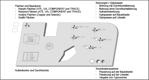
- Drill hole with contact-surface
- Drill hole without contact surface
- Position hole
- Photo marks (on component or solder side)
The aforementioned elements can be distinguished visually. This way the designer can distinguish between different types of drilled holes or photo marks at any time. Further available elements:
- ECAD-components for placement on component or solder side
The ECAD-components can be imported from libraries and may be placed on the PCB with minimal interaction. - Coordinate systems on component or solder side
The coordinate systems are representatives for design elements and components. They also carry information about the type identification number, library-identifier and location for use in the layout system. - Surfaces
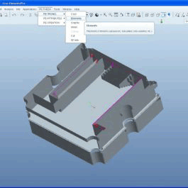
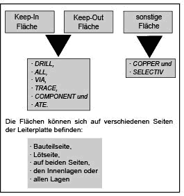
Surfaces serve as representatives of circuit board specific areas. They can either be chosen and placed from a set of pre-defined design elements or be newly created.
Assignment of Attributes
With eTRONIC circuit board specific attributes can be assigned to the aforementioned design elements. These attributes can be changed or deleted at any time. For the description of circuit board specific areas attributes and combinations of attributes will be assigned to surfaces.
After assigning attributes to the surfaces they can be visualized on the circuit board by labels. This allows the designer to review the design status as well as the already used attributes. Furthermore, if inside positions, all positions or both sides is selected, the surface for visualization is automatically mirrored to the opposite side. With the combination keep out-component an interactive query of the Z-offset as well as the height restriction is carried out to describe the barred building volume. After entering these values a 3D-display of the barred building volume will be visualized.
All functions are linked with an automatic layer assignment, so that specific elements or attributes can be switched on or off for matters of visualization or the creation of production instructions. Control and information functions allow the examination and visualization of construction elements and their attributes.
Geometric Analysis with eTRONIC
During geometric analysis the position and form of the circuit board, the construction elements and the components placed on it are examined. The analysis considers:
- all above mentioned construction elements, fitted in by eTRONIC
- any design elements with aforementioned attributes
- the outline contour
- surfaces and their attributes
Development of Circuit Board Panels with eTRONIC
eTRONIC supports the development of circuit board panels. The program automatically recognizes whether a single circuit board or a circuit board panel is processed. The menu sequence of the program is adjusted in accordance. In panel mode additional construction elements as well as own libraries are available (e.g. for the placement of circuit boards or elements for bad circuit board identification). Different configuration files enable the user to adapt eTRONIC to his personal requirements.
Interfaces for eTRONIC
The following interfaces to layout systems for eTRONIC already exist:
| Interface | Layout System | Manufacturer |
| MENTOR INTEGRA THEDA |
Boardstation INTEGRA-Station THEDA |
Mentor Graphics Mentor Graphics INCASES ENGINEERING |
Supported hardware and software:
eTRONIC for Creo is available for the current and supported versions of PTC Creo, PTC Creo Elements/Pro and Pro/ENGINEER.
Please do not hesitate to contact us, if you require more information, or if you are looking for something else.


