SF THERMCUT
Export of Sheet Metal Cutting Data
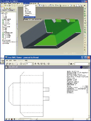
THERMCUT for Creo extracts the silhouette geometry required for NC cutting directly from 3D sheet metal models. The resulting Dxf or Iges files are ready for use in nesting programs without manual modification. Thus, a high degree of automation can be achieved, leading to considerable time savings.
THERMCUT processes arbitrary flat parts as well as bent sheets that have been designed in Creo sheetmetal mode. For bent sheets, an unbent version has to be available as a family table instance.
The silhouettes created by THERMCUT are composed of line segments and arcs. Other curve types like splines or ellipses are approximated with adjustable accuracy by a series of arcs.
THERMCUT application modes
- Part mode: The active part in a Creo session is exported interactively. If it is the generic of a family table, all flat instances are exported. These are recognized via a configurable naming convention.
- Assembly mode: All sheet metal parts in the active assembly are exported. These can either be recognized via a user-defined parameter or via the part geometry. In addition, the user can interactively select the parts to be exported.
- Batch mode: THERMCUT is started from the command line in order to export a larger number of parts. A text file with a list of parts is specified as a command line argument. The graphical user interface of Pro/ENGINEER will not show up.

Fig. 1: Cutting Geometric with additional Information
Other THERMCUT features
- Data for cost calculation (total contour length and number of contours, area, width, height, thickness; values can be assigned to model parameters)
- Freely configurable color, line style and layer of all elements in the output
- Freely configurable text field that can include values of arbitrary model parameters (optional)
- Export of bend axes (optional)
- Export of datum curves (optional)
- Holes with small diameter can be suppressed in the output. Small holes are defined relative to sheet thickness (optional)
Optional module for weld edge preparation
Chamfers, rounds and allowances on the silhouette are marked in the output by user-specified colors and line styles. Dimensions of rounds and chamfers can also be shown in the output.
Supported hardware and software:
THERMCUT for Creo is available for the current and supported versions of PTC Creo, PTC Creo Elements/Pro and Pro/ENGINEER.
Please do not hesitate to contact us, if you require more information, or if you are looking for something else.
